Page 3 - Physical Look - Inside
As always, we opened up the Cooler Master GX 450W power supply to take a detailed look at the interior. Please note that doing this void your warranty, thanks to the warranty seal that is applied over one of the casing screws. But for your interest, we cracked ours open anyway. There are no user serviceable parts inside.
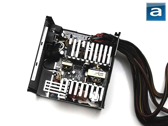
First off, you may have noticed a very similar internal heatsink design as the Cooler Master Silent Pro Gold 1000W reviewed by Preston back in August of last year. That is because Cooler Master has implemented the same "Heat Transfer Technology" that utilizes a unique L-shaped heatsink design to improve airflow inside the unit for lower temperatures. This may be a small reason as to why Cooler Master can get away with a smaller 120mm fan rather than a 140mm fan. In the following section, we will see just how quiet the fan will blow in this unit. As aforementioned in the introduction, the GX 450W is made by a different manufacturer as the other units found in the series. The previous models were manufactured by Seventeam, whereas the GX 450W is manufactured by Enhance Electronics. Enhance is a well known OEM for high quality power supplies. Our photo above shows a broad overhead view of the internal components in the Cooler Master GX 450W.

The first place we look when opening our power supplies would be the transient filter stage. The transient filter stage is the first input stage of a computer power supply unit, and also taking a look at this first gives us a good indication of the overall quality. The Cooler Master GX 450W has two ferrite coils, two metalized polyester X-capacitor, four ceramic Y-capacitors, and one Metal-Oxide Varistor (MOV). This stage of the power supply is flawless. It has one more X-capacitor and two more Y-capacitors than the recommended. I am quite impressed how the company did not skimp on hardware in this area, even though this is a value oriented power supply.

On the primary side, the unit came with one huge capacitor. I cannot fully identify this capacitor, because it appears to be unmarked from what I can see. Usually, PSUs of this caliber would incorporate one or two branded Japanese brand capacitors. For this Cooler Master GX 450W, I am almost 99% sure that the capacitor is Japanese brand by Matsushita/Panasonic rated at 105c. The other 1% makes me think it is a Nippon Chemi-Con, but based on what I know, that is probably not the case. Either one is good though. Lower end run-of-the-mill power supplies usually use 85c rated capacitors.

The Cooler Master GX 450W's active PFC circuit uses one Taiwan Semiconductor GBU806 bridge rectifier, and is controlled by a Champion CM6806 active PFC/PWM controller combo. This component supports up to 8A at 100c at 115V, so in theory, you could pull up to 920W from this power grid (8A * 1 diode * 115V). This is of course at 100% efficiency, which is not going to happen in real life. On the active PFC circuit, one Infineon IPW50R140CP power MOFSET transistor is used, which can deliver 23A at 25 degrees Celsius or up to 15A at 100 degrees Celsius continuously. This transistor presents a maximum resistance of 0.14 ohm when turned on -- commonly abbreviated as RDS(on) -- and a typical resistance of 0.13 ohm according to the manufacturer's data sheet. To clarify, the transistor will waste less power (Higher efficiency) the lower the resistance number. Another two STMicroelectronics STP12NM50 MOSFETs are used in the switching section in forward configuration. Each MOFSET here can deliver up to 7.5A at 100 degrees Celsius in continuous mode, with an RDS(on) of 0.35 ohm and a typical resistance of 0.30 ohm according to the manufacturer's data sheet.

Taking a look on the secondary side, the Cooler Master GX 450W uses capacitors from Teapo, and is labeled at 105c. They come from a different OEM than the single capacitor seen on the primary side. This is quite a nice surprise, as we tend to see 85c secondary capacitors.
On the secondary side are four different rectifiers attached to the heatsink that are in charge of the rectifying process. The +12V out uses two separate rectifiers. The first would be a Vishay 4OCPQ060 rectifier that has a maximum average forward current of 40A (2 diodes * 20A) at 120 degrees Celsius, and a maximum forward voltage drop of 0.68V. The second would be a STMicroelectronics STPS30L60CW rectifier used for direct rectification, and has a maximum average forward current of 30A (2 diodes * 15A) at 130 degrees Celsius, and a maximum forward voltage drop of 0.75V. The +5V output uses a STMicroelectronics STPS30L40CW rectifier with a maximum average forward current of 30A (2 diodes * 15A) at 135 degrees Celsius, and a maximum forward voltage drop of 0.74V. Lastly, the +3.3 output uses a STMicroelectronics STPS40L45CW rectifier with a maximum average forward current of 40A (2 diodes * 20A) at 130 degrees Celsius, and a maximum forward voltage drop of 0.7V. Of course, these numbers will allow one to crunch up theoretical figures as to the current output of each component. However, the amount of power is limited by the other electronics as well. The Cooler Master GX 450W uses a PS223 monitoring IC by Silicon Touch Technology Inc. It supports over-voltage protection, under-voltage protection, over-temperature protection, and over-current protection.

The Cooler Master GX 450W is cooled using a single 120mm fan on the bottom. It is connected to the mainboard using a 2-pin connector, and changes speed according to the temperature inside the power supply. The fan is an ADDA AD1212MS-A71GL, which is a sleeve bearing fan specified at 0.34A 12V, with a maximum rotation of 2050 RPM, and a maximum airflow of 80.5 CFM.
Page Index
1. Introduction, Packaging, Specifications
2. Physical Look - Outside
3. Physical Look - Inside
4. Minor Tests and Conclusion