Page 3 - Physical Look - Inside
As always, we opened up our Thermaltake SMART 730W power supply to take a detailed look at what is going on inside. Please note that doing this at home will void your 5-year warranty, thanks to the warranty seal Thermaltake applied over one of the edges. But for the benefit of you, we cracked ours open so you don't need to, haha. There are no user serviceable parts inside.
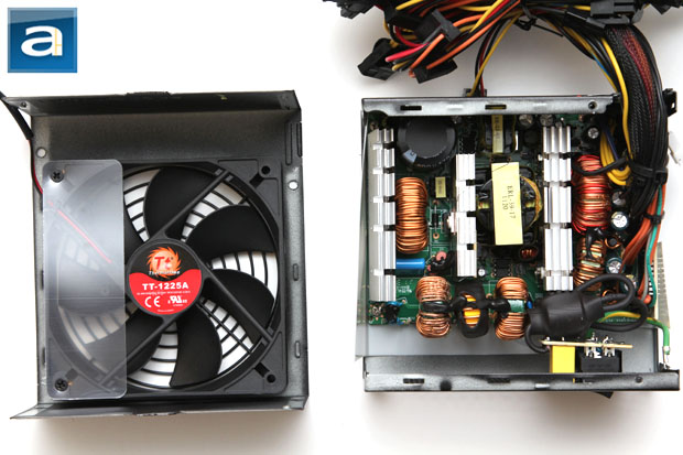
Disassembling the Thermaltake SMART 730W is pretty straightforward, but with a few tricks in between. With two screws at the top, in order to get the shell off the frame, you will need to take out an additional three screws on the side -- two of which are hidden behind the label on the right. Built by HEC/Compucase, our photo above shows an overhead view of the its internal components. At first glance, the build quality appears to be decent, but the soldering job has some room for improvement. Although it is fairly tightly packed inside, the components are well organized for optimal cooling and reduced heat congestion. There are mid-sized three heatsinks inside the power supply, with all of them finned at the top, as you can see in our photo above.

The transient filter stage is the first input stage of a computer power supply, so we will take a look at that first. Thermaltake has done a great job in making sure the SMART 730W met or exceeded the recommended requirements, and this is quite admirable, considering this is more of a value oriented product. The Thermaltake SMART 730W has one ferrite coil, three chokes, one metal oxide varistor, two metalized polyester X-capacitors, and four ceramic Y-capacitors. That is twice as many X capacitors and twice as many Y capacitors than recommended. Considering how many modern day PSUs have missing MOVs, I am happy to see it here, as this component is used to stabilize spikes from the AC line.

On the primary side, we can see one Taiwanese made Teapo capacitor. Taiwanese made units are nothing out of the ordinary for budget oriented power supplies, but we have seen Japanese brand primary capacitors in comparable models from other manufacturers. Our 730W version of Thermaltake's SMART incorporates one 470µF x 400V capacitor. It is rated at 105c; whereas more value oriented power supplies usually use 85c rated capacitors.

The active PFC circuit featured on the Thermaltake SMART 730W uses one Lite-On Semiconductor GBJ1506 glass passivated bridge rectifier, and is controlled by a Fairchild FAN4800IN PFC/PWM controller combo. At 115V, the maximum rectified forward current capacity with heatsink is 15A, so you can theoretically pull up to 1725W (15A * 1 diode * 115V) from the bridge rectifier at 100% efficiency -- of course, this is limited by the fact that it is not 100% efficient, and also neglects the fact that not every component in the system are able to keep up. Three Infineon IPW60R190C6 power MOFSET transistors are used on the active PFC circuit on the Thermaltake SMART 730W power supply, along with an NXP Semiconductor BYC10-600 rectifier diode. Two IPW60R190E6 are used in forward configuration is used in the switching section. All Infineon MOFSETs can deliver up to 12.8A at 100 degrees Celsius continuously. These transistors present a maximum resistance of 0.190 ohm when turned on; with a typical resistance of 0.170 ohm according to the manufacturer's data sheet. This on characteristic is called Static Drain-Source On-Resistance, or commonly abbreviated as RDS(on). The more efficient the component is, the lower the RDS(on) value, since it wastes less power with lower resistance. The NXP BYC10-600 can deliver up to 10A at 78 degrees Celsius continuously.

On the secondary side, we can see more Teapo 105c capacitors. I am pleasantly surprised by this, as most companies usually resort to cheaper 85c units for secondary capacitors. To get everything going, there are four PFC Device Corp. PFR40L60CT rectifiers for its DC +12V output process. The PFR40L60CT's average rectified current is 40A at 25c, peak forward surge current of 250A at 25c, with a Tjunction value of up to +150c. Two Diodes Incorporated SBR30A40CT rectifiers are used for each of its +3.3V and +5V output process. The SBR30A40CT's average rectified current is 30A at 110c, peak forward surge current of 250A at 25c, with a Tjunction value of up to +150c. Using MOSFETs are more efficient than rectifier diodes in the SMART 730W, due to less ohmic loss in the process. Meanwhile, a Silicon Touch PS223 IC provides over/under current, over/under voltage, and over temperature protection on the vertical PCB behind the plastic sheet.

Lastly, we see a modestly sized 120mm fan that provides cooling to the Thermaltake SMART 730W's internal components. It is connected to the mainboard using a 2-pin connector via an adapter cable. Although it is not the largest fan you can fit in a standard ATX power supply, an overhead design provides lots of airflow at lower speeds for quiet operation in most cases. The fan is a Thermaltake TT-1225A, which is a rebranded Young Lin Tech DFS122512H. Further research indicates the TT-1225A/DFS122512H is specified at 0.28A for a maximum of speed of 1700 rpm. The rated airflow is 71.05 CFM and 20.59 Pa static pressure at 33.87 dB of noise.
Page Index
1. Introduction, Packaging, Specifications
2. Physical Look - Outside
3. Physical Look - Inside
4. Minor Tests and Conclusion