Page 2 - Bundle, Chipset, BIOS

Unlike all the high end Gigabyte motherboards we have reviewed up until last year, the P67A-UD5 provides a much less generous bundle than what we have seen in the past. For me personally, this is not a big deal, since I typically use very little of the included accessories anyway. The packaging material has also been simplified to reduce waste, such as using the good old antistatic bag for the motherboard rather than a clear plastic tray with cover. Out of the box, you will receive the following:
- 1x Gigabyte GA-P67A-UD5 motherboard
- 2x SATA cable
- 1x SLI bridge
- 1x I/O backplate
Other than the driver DVD and usual documentations, this is about it. A few extra expansion slot backplates would be nice, but as you will see later on in this review, the P67A-UD5 actually offers a generous amounts of connectors right at the I/O backplate location. However, it probably won't hurt to include a few more SATA cables for a motherboard that has six SATA ports, haha.
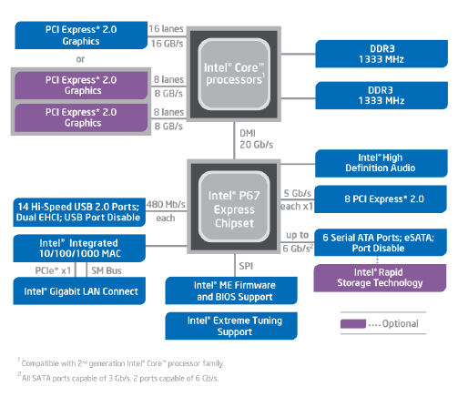
Two chipsets designed for Sandy Bridge processors are available to consumers at press time. Codenamed Cougar Point, the H67 is aimed at mainstream consumers who are not interested in overclocking, but want to take advantage of the integrated graphics. Enthusiasts who want to overclock or use multi-GPU configurations will need to buy motherboards based off the P67 chipset. The Intel Z68 will consolidate the best of both worlds into one later on this year. Common to both the H67 and P67 UEFI support -- pretty much the first time this has hit mainstream with desktop PCs. The biggest advantage to UEFI motherboards are 3TB+ HDD support, more flexible network booting, and much nicer GUIs for the setup screen. As with first generation Core family CPUs, what was previously known as the Southbridge now takes care of the standard connection interfaces such as providing up to 14 USB ports and 6 SATA ports (Of which two of them are SATA 6Gb/s), as well as providing eight additional PCI Express lanes for PCIe based devices such as Ethernet. There is no native USB 3.0 support, so it will still go through a third party controller. Because many Northbridge functions are now on the CPU itself as aforementioned, the P67 chipset doesn't do nearly as much as it did in the past -- thus, Intel has resolved to call it the Platform Controller Hub, or PCH, just like the P55.
The Gigabyte P67A-UD5, as its model number suggests, features the enthusiast P67 chipset. What this motherboard does not have is the UEFI GUI BIOS, and in my opinion is also one of the highlights of Gigabyte's current line of Sandy Bridge products. The main advantages of UEFI is 3TB+ HDD support, more flexible network booting, and nicer GUIs for the setup screen, as compared to the traditional design we have seen for the last twenty years or so. After weeks of usage, I really don't have a problem with Gigabyte's hybrid BIOS design, since we are going through a transition stage right now. I would still like to see a GUI setup screen from Gigabyte in the next generation of products. Before I start digging into the BIOS screens in just a moment, here is a little excerpt on what Gigabyte has to say about their 'Hybrid UEFI BIOS design', for your reference:
Regarding the UEFI BIOS design, there are many discussions recently and some concerns about our traditional BIOS interface design. Therefore, here are some importance of BIOS design that I would like to emphasis on our boards. Our P67 series BIOS is included the UEFI BIOS inside our BIOS, so it can be called as “Hybrid UEFI BIOS.” The most benefit of this Hybrid UEFI BIOS design, it is stable and mature and able to quickly solve any upcoming issues from enthusiast/users and support 3TB drives at 64 bit Windows condition (the most valuable benefit of UEFI BIOS). Furthermore, the advantage of this design, we are able to provide the solution to our current and future platforms such as X58, P55, H55 and AMD series to support the 3TB drives at 64 bit Windows condition as well.
To summarize this, GIGABYTE Hybrid EFI BIOS has provided the same function of UEFI BIOS with the most familiar BIOS interface to the users and also backward compatible with other platforms. This is a stable and mature solution that exclusively provided by GIGABYTE all our users.
On the topic of Intel's Cougar Point recall, one of the transistors inside the Serial ATA 3Gb/s ports in B2 stepping of the chipsets are receiving more voltage than it should, and will degrade over time. The SATA 6Gb/s ports are not affected. Users with high I/O workloads on their SATA 3Gb/s ports will speed up this problem. The degradation will come in the form of increased data transfer error rates; eventually resulting in complete device connection loss. Intel claims that this problem will only affect 5% of users over 3 years, but the has issued a recall on January 31st, 2011 and all major motherboard and computers manufacturers have then stopped shipping motherboards with the faulty chipset. All motherboards have disappeared pretty much within hours from retail on the same day. This is why you will need to wait until B3 stepping P67 chipsets to start shipping before you can make get Sandy Bridge CPUs -- or at least make use of them, unless you know how to work a CPU without a motherboard.

Like all Gigabyte motherboards, the P67A-UD5 uses an Award BIOS. While American Megatrends' BIOS typically uses tabs in addition to pages, Award's BIOS uses a series of menus and pages to categorize each function. Standard adjustments and information links are placed on the left column, and miscellaneous controls are placed on the right column. While I am not going to dig through every menu in the BIOS for this review, I am going to point you to the Motherboard Intelligent Tweaker screens. These screens should pose the most interest, since this is where you do all the overclocking fun -- and the rest should be fairly self-explanatory, haha. Other than some random BIOS hanging issues I have experienced a few times while testing this motherboard, everything works out quite well.
Before we move further into the Motherboard Intelligent Tweaker, let's briefly discuss the fan controlling capabilities of this motherboard. While ASUS motherboards typically do a brilliant job at controlling case fans according to temperature, none of them can control 3-pin CPU fans for some reason. The Gigabyte P67A-UD5 is the reciprocal. It has no idea how to adjust the speed of 3-pin fans connected to this motherboard, but can be tuned to vary the CPU fan speed by voltage or PWM by a simple setting, and it does so spectacularly. The fan speed is determined by a multiplier, which can be set by the end user. In my opinion, the ability of a motherboard to control fans is quite important, and I just wish a manufacturer could make something that can control both the CPU fan and case fans effectively. It is not like it is hard or anything. I am sure it can be done.

The Motherboard Intelligent Tweaker screen further divides into five more sections, as shown in our image above. These sections are labeled M.I.T Current Status, Advanced Frequency Settings, Advanced Memory Settings, Advanced Voltage Settings, and Miscellaneous Settings, respectively. It should be generally clear what the kind of settings are listed under each section, but I will go into these sections in detail in just a moment. Furthermore, we can see at the bottom section of the MB Intelligent Tweaker screen the BIOS version, base clock frequency, memory frequency, total memory size, CPU surface temperature, Vcore, and DRAM voltage -- right from the start. I found this particularly handy and convenient during my overclocking runs.

The M.I.T Current Status screen provides more detailed information with regards to overclocking and voltage. Where you will only find quick data such as BCLK, CPU frequency, and CPU/RAM voltage in the previous page as aforementioned, here you will find information like the CPU name, CPUID, CPU update revision, bus frequency, Uncore frequency, Turbo/Non-Turbo multiplier and frequency of each core, temperature of each CPU core, memory size in each DIMM, as well as current latency settings for each channel of memory. Again, I found this particularly handy while executing overclocking procedures -- and the fact that everything is laid out in organized tables on one screen is very convenient.

The Advanced Frequency Settings screen permits the user to adjust processor settings. Adjusting the CPU clock ratio and BCLK frequency requires the user to enter a decimal value directly, where the base clock value can be adjusted in 0.1MHz increments for fine tuning. Adjusting the memory ratio can be done by entering the desired value directly, and a dialog box will pop up and let the user select the nearest divider. Hitting Enter will bring up a dialog box for the user to select these values directly from a list. Under the Advanced CPU Core Features section are options for enabling or disabling features such as Turbo Mode, SpeedStep, and enabled cores. It is also possible to select XMP profiles from the Advanced Frequency Settings screen as well.

The Advanced Memory Settings screen, as its name suggests, has memory setting options that the user can adjust. You can select XMP profiles in addition to the menu under Advanced Frequency Settings as aforementioned, but here you will also find quick data relating to memory voltage in addition to memory frequency. Timing settings for each channel can be adjusted under their respective timing settings screens, with default latencies in a static column and current/future settings in an adjustable column. Adjusting timing settings involves a dialog box for the user to enter a decimal value, so you won't need to scroll through a long list of numbers to find a desired value.

The last Motherboard Intelligent Tweaker screen I will cover in detail is the Advanced Voltage Settings screen, as shown in our image above. Again, you will find an organized table with a column for voltage type, static normal values, and current/future values that you can adjust. Voltage is adjusted by bringing up a dialog box with a list of voltages -- it is sometimes pretty tedious to go through a long list of voltages before finding the desired value, haha. Good thing you can type in the desired number directly, and the motherboard will automatically what you have entered round to the nearest allowed value. CPU Vcore values start at 0.750V and go up by increments of 0.005V, and reach all the way to 1.70V at the end of the list. DRAM voltage starts at 0.900V and goes up by increments of 0.200V until it reaches 2.600V (Not sure why you would need something that high!). If the desired value is high, the listed or selected value will be written in purple. If the value is extremely high, then it will flash in red.

The Q-Flash function is an integrated feature for the user to flash their BIOS safely and easily. You can flash from any FAT formatted device, such as your USB flash drive. My motherboard came with the F2 BIOS, and Q-Flash does not work when updating to the F6 BIOS. The only workable solution is to flash within Windows using Gigabyte's @BIOS program, which actually worked out quite well. Just a quick note, after flashing your main BIOS and everything works out, you will need to update your secondary BIOS. Otherwise, every time your computer fails to boot due to an overclocking failure, it will automatically overwrite the main BIOS with the older backup BIOS. To do this, you will need to hit ALT+F12 during POST. Unfortunately, this only works with PS/2 keyboards for some reason. Good thing I had a trusty old Microsoft keyboard in my closet, but for those who don't, you are out of luck. This actually took me a while to figure out, and it is quite an inconvenience.
Page Index
1. Introduction, Features, and Specifications
2. Bundle, Chipset, BIOS
3. A Closer Look, Board Layout, Test System
4. Benchmarking Results - Absolute Values
5. Onboard Sound (RMAA 6.2.3) Analyzation
6. Overclocking and Conclusion