Page 3 – Physical Look – Inside

After removing the side panel, you can see the internal design of the DeepCool CH510 Mesh Digital. To be consistent with the exterior, the interior of the case is also painted matte black. The paint is evenly distributed inside the chassis. At bottom of the case, there is a power supply chamber with ventilation holes on top. Not only is it designed to shelter the power supply, but the chamber is also the place for you to put up to two 3.5" HDDs or two 2.5" SSDs. The air for the power supply chamber can come into the case through the dust filter-protected ventilation mesh at the front of the case directly. If your computer is fully loaded with fans, graphics cards, and long radiators, fresh air can be pumped by the fans of up to 360mm radiators into the chassis through the air intakes at the front panel, hit the graphics card, and be expelled out through the exhaust grille at the top panel. If you only plan to use a small radiator or a CPU heatsink with the top ventilation grille covered, the hot air can be expelled out through the rear exhaust grille on the back panel. Note the CPU heatsink clearance for this product is 175mm, which is pretty good. The case can fit graphics cards up to 380mm in length with the front fan mounted. To support long and heavy graphics card, a GPU support bracket is provided. As you can see from the above photo, the bracket's location is adjustable.

As a mid-tower that pushes the size envelope, the DeepCool CH510 Mesh Digital can support E-ATX in addition to regular ATX motherboards, and of course, smaller boards such as mATX and mITX. I noticed all the risers were screwed on to the tray already from the factory. Users do not need to install the required risers according to the size of motherboard that will be used. After bolting the motherboard into position, the heatsink or water cooler block can then be easily installed and removed thanks to the big rectangular opening on the tray.
From the above photo, you can see there is a 120mm fan from the factory on the case’s rear exhaust opening. This is a 4-pin PWM fan that can run at different RPMs controlled by the motherboard. If the user wants to use an all-in-one water cooling system, it requires an extra step to install the radiator directly onto the chassis, which means removing the preinstalled fan. If the all-in-one water cooling system requires the radiator to be mounted on the front of case, the front panel and magnetic dust filter can be easily removed without using any tools.

For the DeepCool CH510 Mesh Digital, the power supply unit needs to be mounted at the bottom of the case. The chassis is raised about 22mm off the ground in order to guarantee the cooling performance of the PSU. There is a mesh opening to accommodate the fan in the PSU as well. Inside the PSU chamber, four nubs with foam pads at the top further elevates the PSU up about 2 to 3mm to further reduce the airflow resistance to the power supply. The grille on the bottom also has an externally removable dust filter pre-installed, such that the quantity of dust sucked into the case is reduced.
As you can see from the above photo, the top of PSU chamber is basically all mesh for better ventilation. The expansion slot covers of this chassis feature stamped holes for the same purpose, but I would prefer for it to be a solid piece for better dust prevention, since I really doubt it makes a significant difference to just have several small holes here.

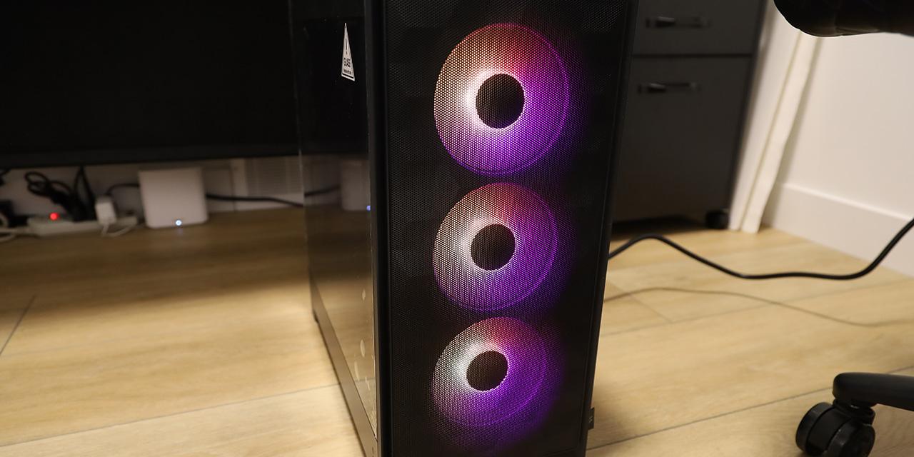
From the above photo, it can be seen the case has openings for up to three 120mm fans or two 140mm fans mounted in the front. For cooling performance, this case can accommodate decent cooling solutions. For example, you can have up to two 360mm radiators mounted on the top and front panels. That aside, you can also have a lot of fans installed. If you really want some fancy looking cooling solution, three ARGB fans can go behind the front panel. The lightly tinted tempered glass side panel will allow the light to shine through.
To keep the computer components clean, the whole front panel can also be easily removed so the user can get access to the front dust filter for cleaning. Note the screen for temperature display in the front panel is connected to the motherboard through a USB 2.0 internal connector. To work on the front mount fans or radiator, users can unplug the 9-pin connector on the screen PCB after popping off the front panel to get the front panel completely out of the way.

Upon removing the right side panel, you will see the other side of the lower chamber and the motherboard tray. Two 3.5" HDD bays on the rack are located to the left side of the power supply area for easy installation and removal of the hard drives. For 2.5" drives, you can have maximum four of them, with two mounted on the 3.5" drive rack and the other two mounted on the back of the motherboard tray.
Regarding cable management, between the motherboard tray and the right side panel, the room for cable routing is about 25mm, which is enough to use. Furthermore, the I/O connector cables are pretty much the same as what you would find from any other case. According to the above picture, there is no Velcro strap provided from factory, which means we need to use zip ties for cable management. Even so, there are minimal tie-down points and no cable routing guides, which I think should be added. By the way, there are two long openings with rubber grommets to route cables. There is no need to worry about the safety of the cables or your fingers during installation thanks to these grommets.
Generally speaking, the interior design of the DeepCool CH510 Mesh Digital is very good. All of the components you need for building a computer can be nicely accommodated and kept cool. It is also nice to see a GPU support bracket included. The paint job quality of the interior is also good. More importantly, there is tons of room to mount large radiators, and there are big openings to allow easy connections between the PSU and the motherboard.
Page Index
1. Introduction, Packaging, Specifications
2. Physical Look - Outside
3. Physical Look - Inside
4. Installation and Conclusion
