Page 3 - A Closer Look, Board Layout, Test System
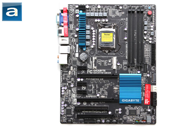
As pleased as I was with Gigabyte since they ditched their signature (But in my personal opinion, fundamentally ugly) blue PCBs last year in their high end offerings, the company continued their line of classy looking black motherboards we have first seen in the P67A-UD5. Sounds familiar? Yep, kind of like what ASUS uses -- except the choice of component colors are still unique. The end result is excellent in my opinion. They also toned down on their use of baby blue and grey heatsinks as we have seen in the past, leaving a clean looking final product that does not over accentuate on one particular mood overtone. Okay, English essay analysis aside, while aesthetics is not really an issue when it comes to internal components of a computer compared to the way the board is built and how well it performs, surprisingly it can be a deciding factor for some users. Of course, the comments on the look are just a personal opinion. As it has gained immense popularity for the last couple years, the Gigabyte GA-Z77X-UD3H, like all Gigabyte midrange performance motherboards, features 100% Japanese manufactured 50,000 hour solid state capacitors, ferrite core chokes, and lower RDS(on) MOSFETS for maximum durability and energy efficiency.
As you can see in the photo of the Gigabyte GA-Z77X-UD3H above, the heatsink configuration is very simple. Because the Z77 PCH is not a whole lot more than just a glorified Southbridge with a 6.7W TDP rating, a simple passive cooler over the chip makes a whole lot of sense. The second heatsink extends over the MOSFETs placed around the processor socket, in which we will cover in just a short moment. Either way, the Gigabyte GA-Z77X-UD3H performs very well, even in cases with not a whole lot of airflow.
As with most motherboards, the ATX 4-pin/EPS 8-pin power connector is located at the top left corner, behind the first USB 3.0 and PS/2 rear external block. It is fairly cramped in this area, especially considering adjacent to the power connector are several other components. It would have been nice to have a downward facing clip rather than an upward facing clip, since it is so close to the edge of the PCB. However, even if that was indeed the case, the blue heatsink will still give you a hard time. Of course, it is easy to criticize than to actually put things into practice. Being an Electrical Engineer who has PCB design experience, I would much rather live with this minor inconvenience than to have this connector moved anywhere else.

Above is a shot of the motherboard at the back. The design is relatively simple and clean; great for those thinking of adding aftermarket CPU cooling solutions. A standard Intel backplate is found here, but all LGA 1155 aftermarket coolers should be designed to work with this backplate in place. Along with the "Ultra Durable 4" scheme Gigabyte's performance motherboards are known to have, they also market the board to have two times the amount of copper used on the power and ground layers of the PCB in order to improve both its cooling and power delivery efficiency to its components. With more copper on these layers, current will flow with reduced impedance, and in turn, less power will wasted into heat. The Z77X-UD3H also has a glass fabric PCB, which is weaved in a much tighter fashion than traditional builds. Gigabyte claims this will provide better humidity protection, but I don't think I ever had this problem in the past, haha. The company also markets ICs with a much higher electrostatic discharge tolerance for better reliability. As always, the RAM socket and expansion card slots uses through hole connectors, as shown in our photo above; SMT (Surface-mount technology) is not capable of withstanding higher mechanical stress required for this purpose.

Within close proximity of the LGA1155 processor socket is the usual array of items -- components relating to the CPU voltage regulator circuit, as well as the lone heatsink over a vertical array of MOSFETs. The heatsink as well as the exposed components in general are low profile, so I have experienced no problems in installing large heatsinks such as the Noctua NH-D14. The CMOS battery is placed right below the heatsink, but since we have a clear CMOS button at the top right corner of the board, the traditional pull-out-the-battery-to-settings trick will probably never be used. As shown in our photo above, you will see one of the biggest things Gigabyte advertises in their Z77 line of motherboards. Rather than using traditional analog voltage regulation system, the company takes it a step further and uses a digital PWM controller array. Marketed as Gigabyte 3D Power, it allows a higher level of precision when it comes to power delivery, faster transient response, and reduced power loss to four crucial power zones: CPU, Intel HD Graphics, RAM, and VTT. As a steady and precise level of voltage control is required for performance tuning, we will explore the board's overclocking potential later on in this review.

The RAM slots are placed a fair distance from the CPU socket, but a little closer than competing manufacturers such as ASUS. Additionally, since the CPU socket is shifted to the middle of the board rather than left-biased like old LGA 775 boards, you may experience clearance issues with the inside slots if you have memory with tall heatspreaders in conjunction with a large CPU heatsink/fan. That said, many RAM manufacturers are now aware of this issue, so low memory kits with low profile heatspreaders are actually a lot more common today than it was a couple of years ago. The ATX 24-pin power connector is placed along the side of the motherboard as far as standard design is concerned, but a good number of user accessible functions are placed adjacent to it as well. From the top, we have a clear CMOS button, system reset bottom, power button, 4-pin fan header, and an array of voltage test points.

Six color coded Serial ATA connectors are angled perpendicular to the motherboard for optimal cabling convenience. They are all native to the Z77 chipset; and supports RAID 0, 1, 5 and 10. The white ports are SATA 6Gb/s ports, while the black ports are SATA 3Gb/s ports. The mSATA connector above the first PCI Express slot is electrically muxed to the fifth SATA port. This means the this SATA port will be made unavailable in the event a mSATA drive is connected.
An auxiliary power connector is situated on the right side of the Intel SATA 6Gb/s ports in reference to our above photo. It provides additional power to the PCI Express graphics slots for enhanced stability. The choice of an angle SATA power port is rather unique; most manufacturers use Molex because it is physically more robust. Meanwhile, a USB 3.0 header is found in its two o'clock position. On the left of the SATA port array, there is a 4-pin fan header, followed by a debug LED. The debug LED displays a code corresponding to the boot sequence, so if there are any issues preventing your system from starting, you won't have to debug a series of beeps just to get things going. The colorful, out of focus block adjacent to the LED display is the case I/O connection headers. It is labeled and color coded for the user's convenience. You can see these more clearly in the following photo.

The expansion slots follow the mSATA port at the top as aforementioned, and are ordered as follows: PCIe x1, PCIe x16, PCIe x1, PCIe x1, PCIe x16, PCI, and another PCIe x16. However, do keep in mind that only the first PCIe x16 slot is a "true" PCIe x16 slot; the second one will have a nice sharing-is-caring session with the first slot if a graphics card is installed to become two x8 slots. This is due to limited availability of PCIe lanes provided by Ivy Bridge and Sandy Bridge core processors. The third slot isn't even a true x16 slot by any means; it only gets four lanes allocated to it from the chipset -- and reduces to an x1 slot when the other PCIe x1 slots are populated. So while you can install a video card there, you won't get full bandwidth. The top PCIe x1 slot will only support very short cards, since the heatpipes will get in the way. Since Intel's Z77 chipset has no native support for PCI slots, the ones found on the Gigabyte GA-Z77X-UD3H are connected to one of the PCI Express lanes by an ITE IT8892E bridge chip.
An array of internal headers can be found at the bottom of the Gigabyte GA-Z77X-UD3H. From the left, we have front panel audio, 4-pin fan, three USB 2.0, and another 4-pin fan header. All fan headers on this motherboard is capable of controlling both 3-pin voltage and 4-pin PWM fans. Next to the case I/O block discussed earlier is a switch labeled 'SW4'. This switch lets you select between the main BIOS and secondary BIOS; the BIOS chips are physically located between the first two PCI Express graphic slots. Generally speaking, good placement of connectors in this segment of the motherboard is usually very challenging, and Gigabyte has done an excellent job of organizing it in an efficient and user friendly manner in my opinion.

The back panel offers a generous array of available external connectors. It features one dual purpose PS/2 connector provided by its ITE IT8728F chip, and a total of six USB 3.0 ports. Please note that only the first two USB 3.0 ports are native to the Intel Z77 chipset; the other four are provided by a VIA VL800 PCI Express to USB 3.0 bridge chip. This is important, because your USB keyboard and mouse can only use the Intel ports until proper drivers are installed. On the topic of USB ports, rather than the standard 900mA power delivery, the Gigabyte GA-Z77X-UD3H is able to provide up to 2700mA on each USB port. It is certainly a very nice touch by the engineers, since devices that charge via USB such as your cell phone can really benefit from this. Additionally, the On/Off charge function allows the USB ports to deliver power even when your computer is shut down.
Moving on, the two eSATA ports you see are provided by a Marvell 88SE9172 chip. An Atheros AR8151 PCIe Gigabit Ethernet controller makes for the lone LAN jack. I was surprised to see only one Gigabit LAN port, and that's from the same company that brought us a whopping four a few years back. Personally, I expected two, haha. Also, an Intel based network solution would have been much better for performance reasons. The rest are audio connectors based off the VIA VT2021 codec; an optical output can be seen in addition to the six standard 3.5mm analog jacks. I think this is a nice departure from the classic Realtek solution. We will see how this stacks up in our tests in just a moment.
Lastly, the series of blue capped ports I tiptoed around in the last two paragraphs are the video connectors. Yep, you are seeing it correctly -- VGA, DVI, DisplayPort, and HDMI -- they are all alive and present. But will they be useful if you are going to use dedicated graphics rather than the integrated GPU on your Sandy Bridge or Ivy Bridge CPU? Well, of course. The Gigabyte Z77X-UD3H supports Lucid Virtu GPU virtualization. If you have a laptop that has NVIDIA Optimus, this is pretty much what it is, but on a desktop level. Plug in all your video cables into the onboard ports, install a discrete graphics card, and dynamically switch between them depending on user demand to save power. It is nice to see this technology made available on a desktop computer!

Our test configuration as follows:
Compared Hardware:
- Gigabyte GA-Z77X-UD3H (Intel Z77; $150 at press time)
- Intel Desktop Board DZ77GA-70K (Intel Z77; $220 at press time)
Common Specifications:
CPU: Intel Core i7-3770K
CPU Cooling: Arctic Cooling Freezer 13 Pro
RAM: G.Skill Ares F3-1600C8Q-16GAB 4x4GB
Graphics: Gigabyte Radeon HD 7870 2GB OC
Chassis: NZXT Switch 810
Storage OCZ Agility 3 240GB
Power: Thermaltake Toughpower XT Platinum 1275W
Sound: Integrated
Optical Drive: None
Operating System: Microsoft Windows 7 Professional SP1 x64
Page Index
1. Introduction, Features, and Specifications
2. Bundle, Chipset, BIOS
3. A Closer Look, Board Layout, Test System
4. Benchmark: AIDA64 CPU
5. Benchmark: AIDA64 FPU
6. Benchmark: AIDA64 Memory
7. Benchmark: BAPCo SYSMark 2012
8. Benchmark: PCMark 7
9. Benchmark: 3DMark 11
10. Benchmark: PassMark PerformanceTest 7.0
11. Benchmark: SuperPI 1M, Cinebench R11.5
12. Onboard Sound Frequency Analysis
13. Overclocking and Conclusion