Page 3 - Physical Look - Inside

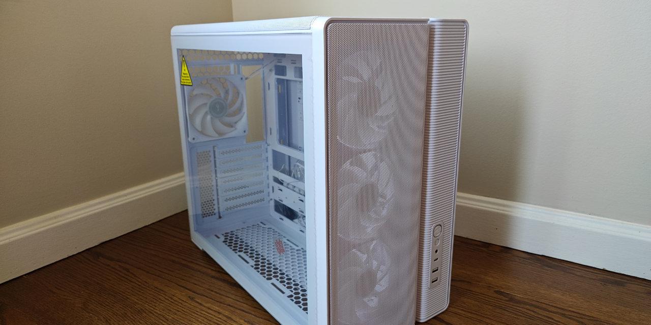
Removing the side panels from the Cooler Master MasterCase MC500M is one of the most unique experiences I have had in a long time. While the right panel is a standard steel side with a pair of captive thumbscrews, the only thing that is the same as other cases is to loosen these screws. Afterwards, you can slide the panel back and let it hang out. As you can see in the photo above, the panel will sit open just like so, allowing you to lift the side out from this position. Similarly, the left tempered glass panel also hangs out without falling, which is really nice so the glass does not come crashing down when released. Releasing this panel involves using some sort of flat head screw or coin to unlock the side panel. Users can turn the middle notch to be perpendicular with the floor to open up this panel. The tempered glass side is also lined with metal on the top and the bottom to avoid any glass on metal action. I really like the way Cooler Master has implemented both of their panels as it prevents any accidental drops. In addition, the gaps between the panels are kept to a minimum, as they both fit evenly to the side of the case without allowing any extra air to get in here.

After you open up the panels, you can get a closer look at the inside of the Cooler Master MasterCase MC500M. The layout is similar to the last Cooler Master case we reviewed, the MasterCase Pro 6 with some exceptions. As such, we have the same included two 5.25" drive slots at the top left corner, along with a hard drive cage mounted right underneath. These are both modular in the sense they can be removed should you want more of an open case. Otherwise, the large chamber is separated by a translucent spotted acrylic panel, with a neat RGB party trick as you will see soon enough. This separation divides the motherboard area from the power supply basement, which is pretty standard. Once again, this divider can be removed if you so desire. The large area with the massive rectangular opening can fit motherboards up to E-ATX in form factor, and down to mini ITX boards too. Overall, the layout still is pretty open, allowing for air to flow from the front to the back. It may not necessarily be the most unobstructed airflow, but parts can be removed to clear it up if you desire.

To get a better picture of the top and back of the inside, I removed the top panel. This reveals how much space there is at the top to allow for ceiling mounted cooling components without interfering with any of the motherboard. With how deep the indentation is, you also would not need these mounting holes to be offset, as it really is far away from the motherboard. At the top, users can put up to two 120mm or 140mm fans, or up to a single 280mm radiator for cooling. From this point, you can also get a closer look at the holes around the motherboard and at the back of the motherboard. These edges have been curved over to prevent users from cutting their fingers or cables on the edges. The top reveals a few more holes to pass the CPU power connector through. At the back, we have the single 140mm fan included by Cooler Master. These are voltage controlled fans and seem a bit cheap compared to the rest of the chassis. Again, it would have been nice to see some of their more premium PWM fans included with this case.

At this angle, you can see the power supply divider and the bottom of the motherboard area. You can also see the seven expansion slot brackets here, each held on by an individual thumbscrew. As for the shroud, this is definitely one difference piece compared to what we have seen before. According to Cooler Master, this is an RGB LED partition plate, which can be controlled through the front panel I/O. With the speckled design of the panel, this piece has RGB lights on the edge that shine through to catch onto these marks. This is definitely a first for any case, and I am really excited to see how this looks like later on in our review. Following Cooler Master's "Freeform Modular System", this panel can be removed as well, with four screws around the case holding it in place. There is no hole in the panel to pass cables through, something I would have liked to see, and there is only a thin slit between the back of the case and the acrylic panel to get all the bottom connectors through. We will see if there is enough space when we do our installation. Otherwise, since the plate is translucent, you can actually see into the power supply area. However, this panel masks the basement enough to hide cables extra cables and connectors.

As mentioned at the beginning of this page, the front of the Cooler Master MasterCase MC500M is filled with a lot of drive options, which is great to see. The top 5.25" and dual 3.5" drive cages are mounted on this bar system to allow users to move, change, or completely remove these components. In addition, extra drive cages can be purchased from Cooler Master to add all the drives to your heart's desire. While there is no Nicolas Cage option, I think Cooler Master has provided a lot of different accessories to fit to anyone's need, which again fits in with their FreeForm ideology. Otherwise, the 5.25" drive bracket is a tool-less option, as the side clips slide to lock the optical drive in place. The 3.5" drive cages are also holding plastic sleds with no tools required here too. They can also hold smaller 2.5" drives, but this would require a few screws to mount them in place. At the bottom we have another dual 3.5" drive cage, which also can be removed if you so desire. Finally, behind all of these brackets are two more 140mm fans included with the MC500M.

Unlike the MasterCase Pro 6, the MC500M comes with a few additional items to help with cable management. The first is a large metal plate which covers the whole left side of the back. The idea is to use this plate to hide the cables from the backside, making sliding the right panel into place easier and cleaning up the extra cables. Behind this metal plate is a large valley for the included front panel cables. These cables include two USB 3.0 headers, a newer USB 3.1 header, connections for the fan and RGB controller, front panel audio, and other I/O wires. You can also route your own cables in here and secure them down with the three Velcro straps included here. Beside the valley are three large cabling holes lined with rubber grommets to hide cables while passing them to the front. These grommets are really flexible and do not pop out of place, which is great to see.
Underneath the large motherboard opening, we have two 2.5" drive sleds to secure SSDs or small hard drives to. However, one of these sleds are occupied already, as we will see shortly. At the bottom of the MC500M, you can see there is the area for the power supply, with more than enough space for 250mm PSUs and the accompanying cables with the dual 3.5" drive bay in place. Removing this drive area will allow for even longer power supplies, though I doubt you will find one that spans this long. Underneath the power supply, we have two strips of rubber to prevent the power supply from creating vibrating noises on the case.

As we mentioned previously, the left 2.5" drive sled is occupied by an included RGB and fan controller. This allows users to connect two more RGB components, such as LED strips or fans. There is also an output to connect to motherboards to synchronize all of the lights. This should work with majority of the major motherboard manufacturers. On the right side, we have connectors for the 3-pin fans. As you can see, an additional three fans can be added and controlled by this controller. At the bottom of this card is the power connector, which thankfully is powered by a SATA power connector, and not a Molex one. While it does have a connector to the motherboard for the lighting, I am a bit confused as to why it does not have a way to control the fans from the motherboard. I would have liked to see this, because it means users would not have to manually change their fan speeds.
Page Index
1. Introduction, Packaging, Specifications
2. Physical Look - Outside
3. Physical Look - Inside
4. Installation and Conclusion