Page 3 - A Closer Look - Disassembly and Internals

Trying to get into the Epomaker EK98 is frustrating to say the least. It is not the most difficult keyboard to get into, but trying to open it up without breaking it is probably worse than shucking a dozen oysters. There are no screws on the exterior of the keyboard at all, meaning it is held in by clips. The clips require a lot of prying, which opens up the potential for irreversible damage. With all this in mind, disassembly is not for the faint of heart. To open the EK98, first remove all the key caps to avoid damage. On the underside, you can wedge guitar picks in between the housing separation, starting from the back. The two sides are a similar story with a lot of sliding and pushing picks deep into the crevices and corners to release the clips. The front is the scariest part, as the construction is different. The seam is front and center with three very fragile latches that needed to somehow be stabbed inwards to release. I do not think this keyboard was built with the intention of being easily disassembled.
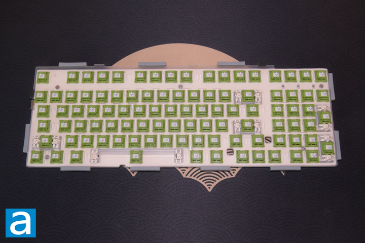
Once the top housing is separated, we can see the internals of the keyboard. The polycarbonate plate is mounted on ten silicone gaskets that rest in between the top and bottom housing. This helps in dampening vibrations when typing.
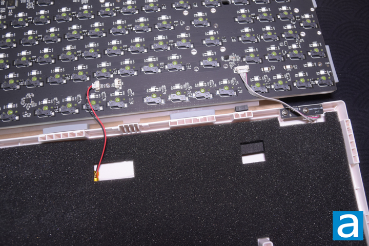
When lifting the assembly with the PCB and plate assembly, there are two separate wires to be aware of. One set of wires near the middle connect the battery, while the other set connects to the USB daughterboard. The bottom housing is where the battery and daughterboard are mounted, with a 4mm piece of black foam present to dampen internal noise. There are two posts in the middle of the back housing to align the upper plate components.
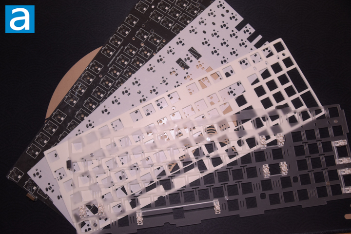
For the plate and PCB assembly, it is basically held together by the key switches. The PCB features 5-pin hot swap sockets, allowing for the switches to be removed easily. The included switch puller is terrible and did not work for me. I used my personal switch puller instead. There are screw holes and standoffs present on the PCB plate, however, they were not utilized. In between the plate and the PCB, there is a 3 to 4mm piece of latex foam that likely contributed to the deeper typing tones. The key switches are mounted on a thinner piece of less than 1mm closed cell foam that is also on top of an additional TPU feeling tape that was present on the PCB. The thin foam likely helped to give the switches a bit more pop in sound, while the TPU tape may have been to help with stabilizer bottoming out. This is probably the most sandwiching material I have seen on a non-custom keyboard. It could probably be further improved with a denser foam behind the PCB on the bottom housing, but that is more of a job for enthusiasts to fine tune it at this point. For an out-of-box experience, plastic housing, and a more budget-oriented wireless keyboard, the sound achieved is quite impressive.
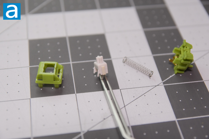
The Peace Lily switches are based on the original Cherry MX design, as the patents expired some time back in 2014. The jade green colored housing is made of polyoxymethylene plastic, also known as POM. The benefit of POM is that it has high abrasion resistance and strength, giving it very good sliding properties. It usually gives the switch a more “thocky” or lower resonance sound. The white stem is made of polycarbonate. This helps the stem to be tough, and is hard enough that changing keycaps should not cause the stem to deform. The spring is 20mm long, which is on the longer side. This should help with stability and linearity of the switch. There is a little bit of stem wobble from side-to-side and even more forward-to-back movement. This movement can make the keys feel more economical and less comfortable when typing due to the extra movement. Fortunately, the stem wobble did not affect the typing experience too much. Considering the switches retail for around $0.25 each, they perform well with a nice and pronounced bottom-out pop.
Page Index
1. Introduction, Packaging, Specifications
2. A Closer Look - Hardware
3. A Closer Look - Disassembly and Internals
4. Conclusion