Page 3 - Physical Look - Inside

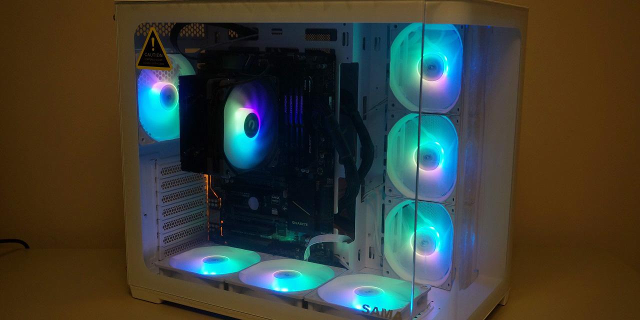
After removing the tempered glass side panels, we can have a closer look into the interior. The black color remains constant throughout the entire case. The PSU shroud covers over the majority of the bottom of the case, while leaving space at the front for a radiator or other cooling options. Underneath the shroud, we have plenty of space for the excess cables to sit. On top of the shroud are two 2.5” SSD mounts, each of them having their own individual cut outs for cables. There is a break between the motherboard tray and the right side of the case to allow for easy cable routes to the front.

Alongside the top resides another cable management cut out. As a novice PC builder, I found this cut out to be satisfactory in fitting the CPU power cable. There is also a 120mm or 140mm fan mount on the top of the case. There is an additional preinstalled 120mm fan in the back. There is a small amount of space to place a fan here, but you must consider the amount of space you need for the CPU cable or the motherboard. There are preinstalled standoffs for an ATX motherboard. There is also a large opening for the back of the motherboard for users to install a backplate for third-party CPU coolers. This will help in the future by letting you install your CPU cooler after the motherboard is installed. The case can support coolers up to 165mm in height.

On the bottom of the case, there are two 2.5” SSD trays as mentioned before. There are two cut outs to allow easy cable routes to them. There is another cutout to the side of the SSD mount designed for the GPU power cable to allow for a cleaner look in terms of cable management. Looking at the clearance for the graphics card, the FSP CMT510 Plus allows for up to 400mm boards. You can see the space at the front allows for a radiator up to 360mm to be installed. The space for the radiator is very large and should not face any problems regarding space for the radiator in this case.
There are three intake fans at the front of the case. These fans have anti-vibration pads, meaning the fans should run silently without any reverberation. These pads are also applied to the pre-installed fan at the back of the case. Unfortunately, the front of the case does not have a dust filter, allowing for dust to enter here. I can understand the choice to not have them as they would affect the aesthetic look of the case, but this is still a bad compromise. Worse yet, there is not much more room from the front due to the tempered glass panel, with just under 10mm of a gap to pull air into the case from the sides of the tempered glass panel. I can feel some of the air being pulled in when I put my hand near the sides of the glass, but it still is not ideal for these three fans to be so choked out for air. As for their lighting, the pre-installed fans can be connected to any motherboard via a 5V RGB header and can be controlled by software like ASUS Aura Sync, Gigabyte RGB FUSION, MSI Mystic Light Sync, and ASRock Polychrome Sync. If your motherboard does not have a 5V RGB header, the RGB button on the I/O can still be used to change the color of the fans. This rotates through 19 different effects, as well as being able to turn off the RGB completely.

The back of the FSP CMT510 Plus looks standard to other cases in the market. The CMT510 Plus does include two vertical hard drive mounts. This is pretty different compared to the usual drive bay at the bottom of the case. These mounts can be found on the left of the case and can also house 2.5” drives. The CMT510 Plus has plenty of cable tie loops to hold down cables. This allows for a cleaner cable management, which is essential for a case with a tempered glass back. It would have been nice to see Velcro straps including in this case to make the cable management have a cleaner look. The fan hub sits at the top middle of the case, allowing an easy solution to routing the fan cables.
Page Index
1. Introduction, Packaging, Specifications
2. Physical Look - Outside
3. Physical Look - Inside
4. Installation and Conclusion
