Page 3 - Physical Look - Inside
As always, we opened up our DeepCool PX1000G 1000W power supply to take a detailed look at what is going on inside. Please note that doing this at home will void your 10-year warranty, thanks to the warranty seal DeepCool applied over one of the attachment screws. For your benefit, we opened ours up, so you do not need to. There are no user serviceable parts inside.
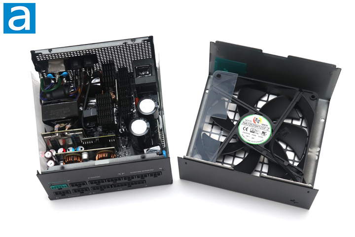
Opening the DeepCool PX1000G 1000W is quite straightforward with the removal of four screws. Taking out the internal components from the enclosure requires the removal of even more screws. The OEM for this power supply is Channel Well Technology or CWT, a reputable OEM since 1993. As we have already mentioned, this is the same platform as the Thermaltake Toughpower GF3 1000W, so it is not surprising the two units look very similar in its layout. It features an LLC half bridge topology with DC-to-DC converters. At first glance, the build quality appears to be excellent. There are three black main heatsinks inside and almost no wires. All of them are located on the primary side.
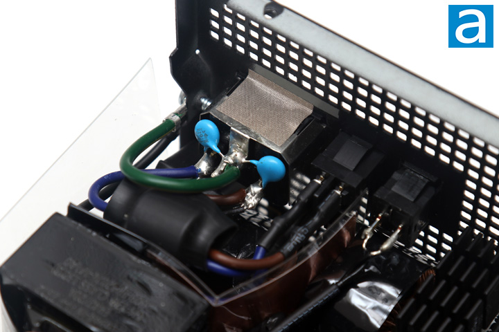
Starting with the transient filter stage, there is a total of two X-capacitors and four Y-capacitors near or around the AC receptacle. This is two times the amount of X and Y capacitors than recommended. In addition, we have two common mode chokes and a metal oxide varistor. The MOV helps with suppressing voltage spikes. Considering some modern-day PSUs have missing MOVs, I am happy to see it here.
The active PFC circuit featured on the DeepCool PX1000G 1000W uses two Yangzhou Yangjie Electronic Technology GBJ2510 bridge rectifiers on one side of the large primary heatsink. At 115V, the maximum rectified forward current capacity with heatsink is 25A each, so you can theoretically pull up to 5750W (25A * 2 diodes * 115V) from the bridge rectifier at 100% efficiency. Of course, this is limited by the fact that it is not 100% efficient and also neglects the fact that not every component in the system is able to keep up.
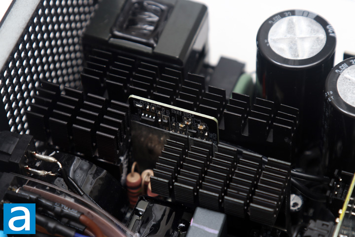
Further down the line, we can see two active PFC MOSFETs, which are Infineon IPA60R099P6 power transistors. Each one is certified for up to 24A at 100c. These transistors present a typical resistance of 99 mΩ when turned on according to the manufacturer's data sheet. This on characteristic is called Static Drain-Source On-Resistance, or commonly abbreviated as RDS(on). The more efficient the component is, the lower the RDS(on) value, since it wastes less power with lower resistance.
On the same heatsink, there is one Cree C3D10060 Schottky diode. Finally, we have two switcher MOSFETs located on another heatsink near the primary capacitors, and these are the STMicroelectronics STF33N60M2. Each of these are certified for up to 16A at 100c. These transistors present a maximum resistance of 125mΩ when turned on according to the manufacturer's data sheet. Champion's CU6901VAC is the switching controller and their CM6500UNX is the APFC controller circuit.
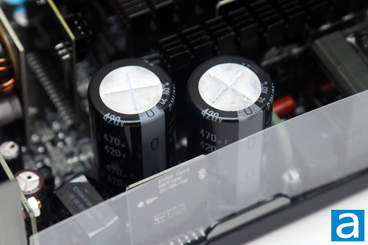
As for the primary capacitors, you can see two Japanese brand ones from Nichicon. Our DeepCool PX1000G 1000W power supply uses two 470µF x 420V for an equivalent capacitance of 940µF x 420V. They are rated at 105c, whereas more value-oriented power supplies usually use 85c rated capacitors.
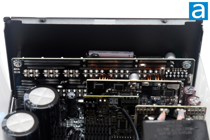
On the secondary side, we can see more Japanese brand electrolytic capacitors from Nippon Chemi-Con and Nichicon rated at 105c. All of the polymer capacitors are also made by the two aforementioned companies. One thing we should note is DeepCool states only full Japanese electrolytic capacitors. In our unit, both the electrolytic and polymer capacitors were made by Japanese companies, but it is not guaranteed to be the case with every unit. Thermaltake claimed 100% Japanese capacitors on their Toughpower GF3 1000W, but we found Chinese-made CapXon polymer capacitors there.
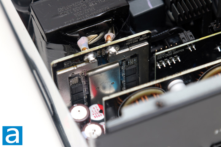
All rectifiers produce the +12V out, while the +5V and +3.3V outputs are generated from the +12V output using a DC-to-DC converter within the power supply unit. A total of eight Infineon BSC014N04LS MOSFETs generate the +12V output, located on a daughterboard near the secondary side of the transformer. Its rated continuous drain current is 125A at 100c. It has an RDS(on) value of 1.4 mΩ maximum and 1.1mΩ typical at 10V.
On a different add-in board, we have the MOSFETs that generate the +5V and +3.3V output from the +12V rail. This includes two UBIQ QN3107M6N and two UBIQ QM3054M6 MOSFETs. These act as the DC-to-DC converter. The QN3107M6N has a drain to source current of 70A at 100c, with an RDS(on) of 2.6 mΩ and a typical resistance of 2.1 mΩ at 10V. The QM3054M6 is certified for 61A at 100c with a maximum resistance of 4.8 mΩ and typical resistance of 3.8 mΩ at 10V. Finally, a uPI-Semi UP3861P can be found on the same board for PWM control.
Other components on other add-in boards include a Weltrend WT7502R monitoring IC, which provides overvoltage, undervoltage, and short circuit protection, as well as the power good signal. The datasheets for all of the components mentioned in the inspection should be found on their respective manufacturer's website.
At the back, we have a large daughterboard covering the majority of the rear panel for the modular cable sockets. All modular sockets at the bottom are soldered directly to the main PCB after the secondary stage. Pin headers join the mainboard and daughterboard to reduce power transmission loss. The output connector configuration can be seen on the previous page.
Overall, the internal build quality of the DeepCool PX1000G 1000W power supply is excellent. Components are arranged very well for optimal cooling with almost no wires running around inside, and solder points on its black PCB is quite clean in general. Component choices here are also of good quality for this power output.
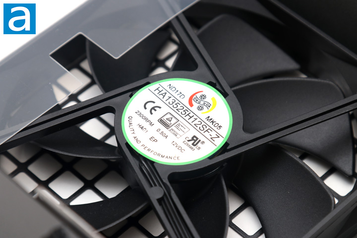
Mounted to the outer shell of the DeepCool PX1000G 1000W is a 135mm fan to provide cooling to the internals. This is connected via an add-in board with a 3-pin connector. The model of the fan is Hong Hua HA13525H12SF-Z, which is a fluid dynamic bearing fan specified at 0.50A for a maximum speed of 2300 RPM. With the zero RPM fan mode active, it will not start moving until the power supply is loaded to approximately 400W. As such, depending on your power draw in your system, the power supply could remain off for the most part, and even when it is on, the fan speed will vary with load. Fluid dynamic bearing fans generally have a longer lifespan compared to sleeve bearing fans, making it quite fitting for a power supply intake fan.
Page Index
1. Introduction, Packaging, Specifications
2. Physical Look - Outside
3. Physical Look - Inside
4. Minor Tests and Conclusion