Page 3 - Physical Look - Inside

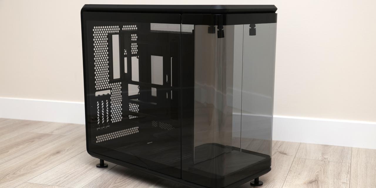
Here is a quick top view snapshot of the internals of the Thermaltake Armor A30. Before you go on questioning what I have done, I have simply removed the power supply bay, so you can get a clearer picture without having so much visual information crammed into your brain. I will go into further detail about the power supply bay in just a moment. As far as the top panel goes, there is really not too much to talk about; other than the fact it has a huge fan powered by a 4-pin Molex connector. To remove the top panel, you will need to remove three corresponding thumbscrews, slide the panel back, and lift. The removable motherboard tray requires six additional thumbscrews to be detached before it slides out. The rear exhaust fans are also powered through a 4-pin Molex connector from your power supply. Once again, the top fan comes with no dust filters, as mentioned on the previous page.
Diverting our attention for a brief moment back to the removable motherboard tray, we can see here it will support both micro-ATX and mini-ATX motherboards. The physical dimensions of the motherboard tray is a perfect 9.6" x 9.6" square, which is about right for a compact computer case. Taking a closer look, you will notice all the risers are permanently installed onto the tray, so you will have one less thing to worry about when it comes to the installation process. However, please do be careful not to break any of them off, although I would say that Thermaltake has done a commendable job in making sure they are not flimsy in any way. You may also be wondering how much components you can cram into so little space. Before you take out your measuring tape, you will be relieved to know I have already taken out mine to double check with Thermaltake's specifications. It measures to 266 mm in height, 291 mm in width, and 456 mm in depth. For our fellow Americans down south, that's 10.5" by 11.5" by 18.0", so you would not have to pull out your converters.

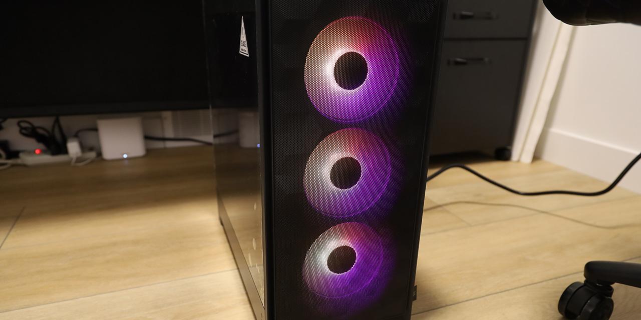
Here is a cleaner look at the removable front panel, with the front intake fan seen just behind the ventilation holes. Of course, the front panel would have a dust filter for obvious reasons. If you decide to utilize your 5.25" and 3.5" drive bays, you can easily remove the dust filters simply by clipping them off on both sides. And of course, we have a glimpse of the front panel connectors on the lower left corner. For those who are concerned about their cabling job, you may be able to fit a couple of cables through here before the rest gets messy.

Taking a closer look at the drive bay area, we can see the hard drive rack is mounted on the bottom with a screw and some clips. After unscrewing it, you will need to slide it forward to totally remove it for easier installation of hard drives. You will also have the choice to install a solid state drive at the very top of this rack, as it gives you screw holes here to mount it. As shown in our photo above, I have conveniently removed the 5.25" and 3.5" drive racks, so it would be much more convenient for installation of accessories. Taking a closer look at the 5.25" bays, another two thumbscrews are used in holding the rack in place. Removing them and sliding the tray back will give you more working room with the 3.5" bays and front area.

This is the power supply bay. Yes, it is indeed a big fat hog, so remember when you are installing your heatsinks, try to remember this area will be very crowded. It is much easier to change out a heatsink than a power supply, and you will understand why when you get to do the cabling job yourself. This bay is screwed in via a thumbscrew on the back panel, as aforementioned; as well as six tiny Philips head screws, three on each side of the bay.

If you ever decide to switch out your CPU heatsink, keep in mind the removable motherboard tray does not provide you with any rear openings, so heatsinks that require aftermarket backplates will take some extra work to be installed onto the motherboard. Considering how much room the Thermaltake Armor A30 gives you, I doubt you will be using heatsinks large enough to put any real stress on your motherboard anyway -- especially those requiring you to use aftermarket backplates. The bottom/back side of the removable motherboard tray offers you next to no room at all for your cabling job, but being a removable tray renders this unnecessary anyway, since half your build will take place outside the chassis. Near the middle, you will be able to spot the groove that I was talking about on the previous page -- but of course, it is seen as a bump on this side. Three similar bumps are lined vertically to support the removable motherboard tray.
On the other side of the horizontal bump are two rubber grommets for vibration dampening, as well as softening the impact when you shove the removable motherboard tray back in. Beyond that are the 3.5" bays and front panel fan; barely covered up by the 5.25" bays mounted in a removable tray on top.
Page Index
1. Introduction, Packaging, Specifications
2. Physical Look - Outside
3. Physical Look - Inside
4. Installation and Conclusion
