Page 3 - Physical Look - Inside

As always, we opened up our ENERMAX Revolution III S 1000W power supply to take a detailed look at what is going on inside. Please note that doing this at home may void your 13-year warranty, thanks to the warranty seal ENERMAX applied over one of the screws. However, this one is easy to get around. Either way, for the benefit of you, we cracked ours open, so you do not need to. There are no user serviceable parts inside.
Disassembling the ENERMAX Revolution III S 1000W was straightforward with the removal of four Philips head screws. Taking out the internal components from the enclosure requires the removal of six more. Our photo above shows an overhead view of its internal components. RSY is the OEM. It features an LLC full bridge topology with DC-to-DC converters. At first glance, the build quality appears to be pretty good. There are three main heatsinks inside. The biggest one is painted red, located on the primary side. Additionally, there are two smaller sized heatsinks in their original aluminum finish on the secondary side.

Pulling the enclosure apart, and we got straight to the internal inspection. The transient filter stage is the first input stage of a computer power supply, so we will take a look at that first. The ENERMAX Revolution III S 1000W has one metal oxide varistor, two metalized polyester X-capacitors, four ceramic Y-capacitors, and two ferrite coils. This is two times the amount of X and Y capacitors than recommended.

The active PFC circuit featured on the ENERMAX Revolution III S 1000W uses one bridge rectifiers on the large red heatsink. Unfortunately, I was unable to identify their brand and part number, as the chip is clipped between the heatsink, rendering it not visible from either side.
Further down the line, on the side of the large red heatsink that faces out, we can see two Maplesemi SLF60R090E7 power transistors. Each is certified for up to 27.2A at 100c. These transistors present a maximum resistance of 70 mΩ and typical resistance of 53 mΩ at 10V, 25c when turned on according to the manufacturer's data sheet. This on characteristic is called Static Drain-Source On-Resistance, or commonly abbreviated as RDS(on). The more efficient the component is, the lower the RDS(on) value, since it wastes less power with lower resistance.
One Diodes Incorporated DSC10A065 boost diode next to the two SLF60R090E7. Four Convert Semiconductor CS25N50FF MOFSETs, located to the right of the DSC10A065 on the same heatsink, are used as the main switchers on the Revolution III S 1000W power supply. Each is certified for up to 25A at 100c and typical resistance of 180 mΩ at 10V.
For the +5VSB circuit, there is a First Semiconductor FIR4N70L VDMOSFET and Pingwei PS1060L Schottky barrier rectifier located on the main PCB under the rear connector daughterboard.

On the primary side, we can see one Japanese brand Rubycon capacitor. 100% Japanese brand electrolytic capacitors are specified in the marketing material, so this is to be expected. Our 1000W version of ENERMAX's Revolution III S power supply incorporates one 560µF x 420V capacitor. It is rated at 105c, whereas more value-oriented power supplies usually use 85c rated capacitors.
A Texas Instruments UCC28180 PFC controller and Sync Power SPN5003 MOSFET can be spotted on the vertical add-in board left of the red heatsink in the photo above.

On the secondary side, we can see more Rubycon capacitors rated at 105c. There are also some Unicon capacitors, which are also Japanese brand capacitors, although not common in power supplies. All rectifiers produce the +12V out, while the +5V and +3.3V outputs are generated from the +12V output using a DC-to-DC converter within as with modern high efficiency power supplies. Four AGMSemi AGM4012C power MOSFETs are responsible for generating the +12V output, with two on each of the two smaller heatsinks. The AGM4012C's rated continuous drain current is 154A at 100c. It has an RDS(on) value of 1.4 mΩ maximum and 1.1 mΩ typical at 10V, 25c.
Four Infineon BSC0906NS MOSFETs are responsible for generating the +5V and +3.3V outputs, located on the opposite side of the larger add-in board in the above photo. The BSC0906NS's rated continuous drain current is 40A at 100c. It has an RDS(on) value of 4.5 mΩ maximum and 3.8 mΩ typical. On the same PCB, we can find two ANPEC APW7164 chips, which are the PWM switching controllers.
An IN1S3131-SAG supervisor IC can be spotted on smaller add-in board close to the edge in the photo above. The datasheets for all components mentioned in this review can be found on their respective manufacturer's websites.

Here is a shot at the bottom of the main board. It has a black soldermask. There are no components of significance placed here.

At the very back, we have a medium-sized daughterboard covering the entire rear panel for the modular cable sockets. All connection points are soldered directly to the add-on PCB after the secondary stage to reduce power transmission loss compared to having wires. The output connector configuration can be seen on the previous page.
Overall, the internal build quality of ENERMAX Revolution III S 1000W is pretty good. Components are arranged very well for optimal cooling with practically no wires running around inside, and solder points on its black PCB is quite clean in general. I would say the ENERMAX Revolution III S 1000W is mixed with regards to the selection of components used under the hood. Capacitors are top notch, and we also find some Infineon MOSFETs for the minor rail outputs. However, the Chinese brand ICs are relatively unknown in terms of performance and longevity.

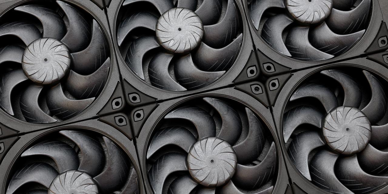
Lastly, we see a 120mm fan that provides cooling to the ENERMAX Revolution III S 1000W's internal components. It is connected to the controller using a 2-pin connector. A 120mm fan is rather small nowadays for a power supply with a bottom mounted fan, but this is the largest one that can fit into this small 14cm enclosure. If not a lot of heat is being generated, noise will be kept to a minimum.
The fan is a Globe Fan S1202512L, as shown in our photo above. The S1202512L is a fluid dynamic bearing fan specified at 0.18A for a maximum speed of 2000 RPM, 90.92 CFM air flow, 3.06 mmH2O air pressure, and 34.0 dB(A) of noise. The fan is not supposed to activate until the PSU is loaded up to approximately 350W. As such, it should remain off for the most part, and even when it is on, the fan speed will vary with load. Fans with fluid dynamic bearings generally have much longer lifespans compared to sleeve bearing fans and are quite suitable for this application.
Page Index
1. Introduction, Packaging, Specifications
2. Physical Look - Outside
3. Physical Look - Inside
4. Minor Tests and Conclusion