Page 2 - A Closer Look - Assembly and Internals
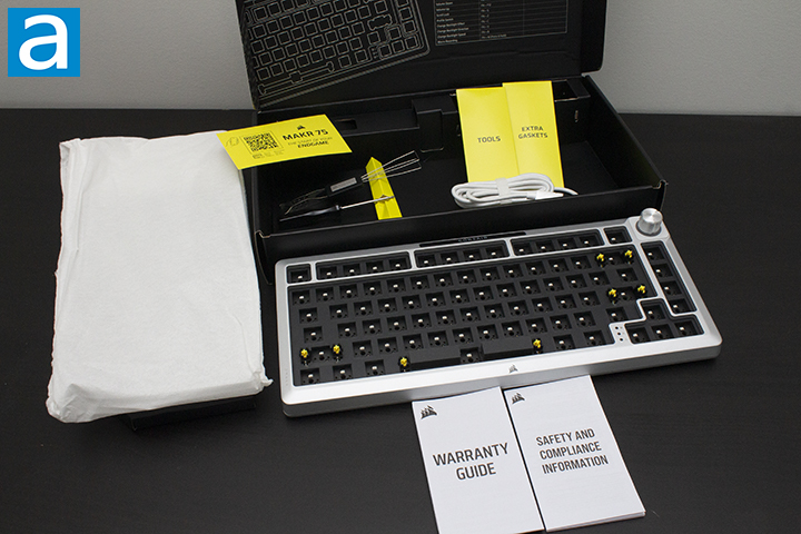
Upon unpacking the Corsair MAKR 75 barebones kit, we are greeted by the keyboard pre-assembled for the most part. This is really good for someone who is just entering the custom keyboard scene, as they are likely to only want to buy switches, put them into the keyboard themselves, then put the keycaps on top. In our specific case, it does add a little extra work, but that is not an issue. Having the keyboard assembled like this out of the box also aids in showing the buyer where each layer of foam resides naturally. Inside the box comes with a cable, extra gaskets in case you lose some, and all the tools required in taking apart the MAKR 75. Given we were provided the Wireless Module and LCD Screen, we will be installing both into the MAKR 75.

We begin by taking apart the keyboard using the including hex key. There are nine screws around the bottom frame of the keyboard that must be removed to enable you to remove both frames. It is important to note that the pre-installed knob will be attached to the PCB via a cable. I personally find it easier to remove the cable from the knob by wiggling the sides until the cable slides out of place. After this point, the keyboard should be broken into three main portions: The PCB, top frame, and bottom frame. The order in which you install each component is completely up to you, but I personally feel it is easier to install the Wireless Module prior to installing the switches. This is because I found it easier to grip the PCB, but your experience may vary. The order I proceeded with started by installing the Wireless Module, installing the LCD Screen into the top frame, installing the switches, connecting the LCD Screen to the PCB, then finally reassembling the keyboard.

The Wireless Module is actually surprisingly simple to install, being plugged in directly to the PCB, rather than using a cable. There are little indicators on the Wireless Module used to line it up with holes placed in the PCB to keep the module in place and secure. I will make it clear that you do not need to remove the foam beneath the PCB prior to installation, as Corsair has taken note of this, and the installation provides an adequate amount of space for the foam. The PCB and Wireless Module will essentially be sandwiching the foam between them. You will know you have successfully installed the Wireless Module when the PCB begins to light up, as the PCB is defaulted to be on. That brings me to the controls. At the top of the PCB, you will find a switch and two buttons. The switch will turn on and off the PCB, while the two buttons function as a SLIPSTREAM Wireless and Bluetooth button. SLIPSTREAM Wireless is Corsair’s name for their 2.4GHz adapter. To access this when the keyboard is fully built, you will have to swap out the top Corsair badge with the provided alternative badge. I recommend pinching and being very gentle with the badges, as they are very fragile and will snap if not done carefully. I personally pinched out the clips until I could slowly wiggle them out. Installing the new badge was as simple as pushing it in. When reassembling, make sure the switch is aligned with the badge.

To install the switches, all you need to do is simply insert them into each slot. As long the PCB, foam, and plate are aligned correctly, there should be no issue with just pushing the switches in. I will note for anyone doing this for the first time, you should pay attention to where the pins are, as they will only work in one direction. In this case, we have north facing LEDs, meaning the pins should be facing south. Most keyboards use south-facing LEDs to avoid the issue of Cherry interference, so you should account for this if you are going to use alternative switches and keycaps. Corsair’s switches should have no issue with Cherry interference, as their top housing for the switches are altered to account for the issue. When installing the switches, make sure that they are fully clipped in. To do this, you can wiggle the switch and pull the plate against it. Prior to reassembling, I would recommend testing the switches to make sure all of them are working by plugging in the PCB and typing away.

Moving on to the LCD Screen, we will start by removing the knob. The knob can simply be unplugged then unscrewed at three different points off of the top frame. Next, you will pull off the physical knob so the module can be removed. You will have to unclip a border out of place, which will be replaced by another border used for the LCD Screen. To install the screen, simply insert the border to the top frame of the keyboard. Following this, we will use the previous three screws to secure the LCD Screen into place. Lastly, we will need to plug it into the PCB using the same cable the knob used.

To put the keyboard back together, we will simply be reversing the steps we took to take it apart. As previously mentioned, ensure the power switch is aligned with badge and the screen is plugged in. The same goes for the knob if you unplug it. Everything should be fairly easy to line up, as Corsair has created specific points throughout the enclosure that lines up the case with the PCB and plate. Upon screwing the top and bottom frame together, you can now begin putting the keycaps to finish off the keyboard. Voila, the keyboard is complete, and you are free to use it however you like.
Throughout the whole build process, I was surprised with how compact the Corsair MAKR 75 was. The keyboard was completely filled with foam and was actually quite thin for a keyboard. Furthermore, the plate uses eight gasket socks, with two on the top and six on the bottom. The uneven spread is likely due to the placement of the USB Type-C port. . This begs the question, how do the gaskets actually perform with such limited space? As you may expect, not all that well. I found the MAKR 75 to be quite stiff, so if you are looking for a softer typing experience, this may be an issue for you.
Moving on to stabilizers, we have PCB mount Cherry stabilizers. If you are unfamiliar, there are two main designs of stabilizers, which are Cherry and Costar. In both cases, these are used to maintain balance in the longer keys and stabilize them, as the name implies. Cherry ones will have stems matching the bottom of most keycaps, while Costar has a wire hooked into a hoop on the keycaps. The main issue with Costar stabilizers is how they are a rattly mess, and there is practically nothing you can do about it. Cherry stabilizers also rattle, but there are ways to reduce the sound, making it the superior choice.
There is also a large difference between plate mount and PCB mount stabilizers. Generally, there are three types of mounting method, including plate mounting, screw-in, and clip-in. The latter two are PCB-mounted. I personally prefer screw-in stabilizers, as they stay in place the best out of the three options, followed by clip-in. As the Corsair MAKR 75 is made to be customizable, the usage of screw-in stabilizers makes a lot of sense, as the user can tinker with them all they want by taking apart the keyboard and has the extra security that they will not fall out.
Page Index
1. Introduction, Packaging, Specifications
2. A Closer Look - Assembly and Internals
3. A Closer Look - Hardware and Software
4. A Closer Look - Configurations
5. Conclusion