Page 3 - A Closer Look, Board Layout, Test System

The Gigabyte G1.Sniper follows a pretty standard layout around the board, with added touches such as the gun rail inspired heatsinks on an appealing matte black circuit board. In my opinion, the board is very satisfying to look at (Especially in a windowed chassis), as the Northbridge heatsink also glows green thanks to an array of LEDs when powered on. Of course, your decision on whether or not you will get this motherboard based on aesthetics alone is truly subjective. Around the G1.Sniper, you will not find 100% Japanese brand solid state capacitors. Wait a second. Is that bad? Absolutely not. The ones that are not solid state are related to its audio subsystem. What we have here are Nichicon MUSE ES series and MW series bi-polarized audio grade capacitors, used to provide the best resolution and expansion of sound, desirable for its high performance and superior audio filtering characteristics. They are the same ones found on the Auzentech X-Fi HomeTheater HD, and this is the first time we have seen something this serious on motherboard integrated sound.
As you can see from the photo above, the Gigabyte G1.Sniper has an L-shaped heatpipe tinted in a gunmetal color. This design dissipates heat from two of the four sides of the CPU socket beginning from the Southbridge (Represented by the heatsink that looks like a magazine), which then goes through the Northbridge near the center of the board, and finally to the end of the heatpipe on the left side of the CPU socket. The Northbridge is essentially in charge of the PCI Express lanes that provide access to the graphics slots as discussed on the previous page, while the control over the memory lanes is on the CPU itself, and the Southbridge located near the bottom right handles the rest of the stuff.
One thing to note here is that the G1.Sniper is one of the rare boards that feature a dedicated LAN processing chip. Not only does it have a BigFoot Killer E2100 NPU, Gigabyte also installed Creative's high end CA20K2-2AG HF X-Fi APU/DSP as part of the motherboard -- with real X-RAM, too. We will cover that in detail in just a moment.

A shot at the back side of the motherboard, showing its clean design. Those that own heatsinks utilizing aftermarket backplates will have nothing to worry about. You will find Intel's backplate here, but heatsinks designed for LGA 1366 will have no problems fitting their respectively heatsink backplate on with this plate in place. If you have noticed, there is one feature on this motherboard that is advertised on many high end Gigabyte and ASUS boards. There are two inner layers of copper integrated into the PCB layers, used to improve its cooling efficiency by spreading the heat as evenly as possible all around. Screws are also evident on this side for a better and more secure mount of the various heatsinks situated on the other side. On the topic of capacitors, the use of surface mounts is evident. But as far as pins are concerned for components such as RAM sockets and PCIe slots, they tend to stick out, since SMT is not capable of withstanding this higher mechanical stress.

Taking a close look around the LGA 1366 socket area, we are able to identify the usual array of components related to the CPU voltage regulator circuit, including a decent array of chokes and a couple of gun rail inspired heatsinks on the L-shaped heatpipe. They are slightly taller than what most heatsinks would be, as I have had slight issues installing larger heatsinks such as the Noctua NH-C14 with a fan on the underside. Generally speaking, you may be able to get away with it with no more than a couple of millimeters in clearance. Gigabyte uses a regular voltage regulator module on the G1.Sniper with an 8-phase power design. Working in conjunction with the Dual CPU Power and Driver MOSFETs, this would deliver more power to the CPU while maintaining system performance and power stability. I am actually quite surprised by how little phases there are, especially for something of this caliber -- since even the P55A-UD6 reviewed by my colleague Jonathan last year has a 24-phase power design. I am not saying it will make a huge difference in quantity (Eight is still plenty), but generally speaking, the more the better.

The RAM slots are placed a reasonable distance away from the CPU socket in standard triple channel array configuration. Although this may not be an issue for most of us, if you happen to have a very large heatsink, having taller heatspreaders on your RAM may be an issue of physical interference with your CPU heatsink/fan. The ATX 24-pin power connector is placed along the side of the motherboard, which is quite standard. On the side note, if you have noticed from this angled shot, and by reference from the mounting hole to the edge of the motherboard, the G1.Sniper is measured to be approximately two centimeters wider than a standard ATX motherboard. It will still mount in standard mid-tower cases, but you might need to watch your clearance on the right hand side.

Eight color coded Serial ATA connectors are angled perpendicular to the motherboard for optimal cabling convenience. The first six colored black are 3Gb/s ports native to the X58 chipset, which supports RAID 0, 1, 5 and 10; while the two white ports are controlled by the Marvell 88SE9182 6Gb/s controller and supports either RAID 0 or RAID 1. As you can see from the photo above, although this is an X58 board for first generation Core i7 processors, there are no legacy PATA or floppy connectors. From this angle, you can see the dual BIOS chips behind the Southbridge heatsink, and JMicron JMP262 controller located between the Southbridge and the SATA ports for the eSATA ports at the back panel.
It is important to note the Marvell 88SE9182 6Gb/s controller is connected to the Southbridge via one PCI Express 2.0 lane only. A single PCIe 2.0 lane provides up to 500MB/s bandwidth, meaning the SATA 6Gb/s ports are physically capable of doing up to 4Gb/s only. Although you will bottleneck new SF-2281 based SSDs like the OCZ Vertex 3 Max IOPS, you fortunately won't be too far off. That said, it would have been better if Gigabyte bridged two PCIe lanes together to allocate full bandwidth to the SATA 6Gb/s ports for maximum performance.

Before getting into the PCIe slots, you may have noticed BigFoot Killer E2100 NPU on the left side of the Northbridge. Gigabyte claims that it has 1GB of dedicated DDR2 memory to divert some of the network traffic from the CPU, so it is freed up to go about other tasks. This is one of those things that are nice to have, but not necessarily a necessity -- with today's fast processors, I doubt it really makes a difference compared to a good integrated network controller like Intel's 82579V. Moving onto the expansion slots, from top down, we have two sets of PCIe x16 and x1 slots in alternating order, followed by a PCIe x8 slot, and a legacy PCI slot. With this arrangement, the end user is able to utilize up to three graphics cards in CrossFireX or SLI mode. This arrangement allows you to easily fit dual slot graphics cards, and it is not likely you will need to install a sound card anyway thanks to the awesome onboard sound, haha.
What I really like about the G1.Sniper is that it has a high-end PCI Express based audio processor, which is the same one found on the awesome Auzentech X-Fi HomeTheater HD reviewed by my colleague Jonathan back in March of last year. This includes Creative's renowned CA20K2 APU/DSP, featuring 51.1 million transistors, providing hardware accelerated audio, and capable of handling 10,000 million instructions per second. Also featured on the APU/DSP are 24-bit digital audio input/output, eight audio input and eight audio output interfaces (I2S, I4S, I8S I16S, S/PDIF or CDIF), 24-bit/192kHz stereo playback, and 24-bit/96kHz 7.1 playback. An embedded RISC control processor is used to reduce PCI Express induced latencies. Adjacent to the CA20K2 is a Hynix H5DU1262GTR-E3C 64MB DDR memory chip to serve as the X-RAM to store audio buffers. Nichicon MUSE ES series and MW series bi-polarized audio grade capacitors are also used, as aforementioned. On the topic of audio capacitors, the Nichicon MW series are small orange capacitors rated at 33uF @ 16V, while the Nichicon MUSE ES are green capacitors rated at 33uF @ 16V. This is a truly legitimate implementation of Creative's X-Fi APU/DSP, and a prime example of audio done right on a motherboard. In a sense, it is probably even better than dedicated cards like the Auzentech X-Fi Bravura!
Meanwhile, its operational amplifier, also known as an OpAmp, used with the X-Fi integrated sound system is a STMicroelectronics C4558. It is advertised for its low noise and high speed from its manufacturer, and is capable of driving up to 200Ω loads. A Cirrus Logic CS4882-CQZ 114 dB 192kHz 8-channel digital to analog converter (DAC) is also found on board, and has a dynamic range of 114 dB and -100 dB THD+N. Meanwhile, an AKM 53588ET analog to digital converter (ADC) does the opposite job, which provides up to 96KHz 24-bit analog to digital conversion. A Texas Instruments LC245A optical bus transceiver IC is also installed. It features a 3-state output for optical and coaxial S/PDIF connections.

Gigabyte offers a good amount of connectors at the back panel. In order from left to right and top down, we have a PS/2 mouse and keyboard, coaxial S/PDIF output, overclock button, two sets of USB 2.0 and eSATA/USB combo, two USB 3.0 ports powered by Renesas's D720200 chip, a RJ45 LAN port controlled by Marvell's 88E1118R controller connected to the BigFoot Killer E2100 network processing unit (NPU), another two USB 2.0 ports, and finally, a set of analog 3.5mm jacks and an optical S/PDIF out connector courtesy of the Creative X-Fi based integrated sound.
For those who are looking into overclocking their system, but are unfamiliar with how to set these settings properly in the BIOS, the overclocking button on the back I/O panel provides users with a simple solution. With the press of a finger, this will automatically overclock your system for you. Keep in mind that the auto settings may not be as optimal than when you manually enter in the values in the BIOS, so in my opinion, if you really want to overclock, just learn to do so manually -- don't be lazy.

During operation, five green LEDs light up on the heatsink of the Northbridge.
Our test configuration is as follows:
CPU: Intel Core i7-930 @ 2.80 GHz
CPU Cooling: Noctua NH-C14 (Single Fan Top)
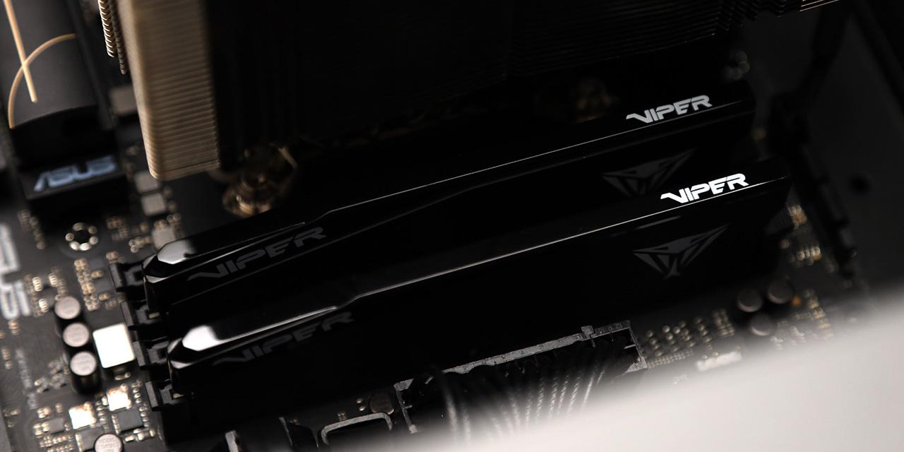
RAM: Patriot Extreme Performance Viper II Sector 7 Series PC3-12800 6x2GB
Graphics: HIS Radeon HD 6870 1GB
Chassis: Cooler Master Storm Enforcer
Storage Western Digital Caviar Green 1TB
Power: Cooler Master Silent Pro Gold 1000W
Sound: Integrated Creative X-Fi
Optical Drive: Asus DRW-24B1ST 24x DVD-RW
Operating System: Microsoft Windows 7 Professional x64 SP1
Compared Hardware:
- Gigabyte G1.Sniper (Intel X58, $430 at press time)
- Asus P6T (Intel X58, $250 at press time)
Page Index
1. Introduction, Features, and Specifications
2. Bundle, Chipset, BIOS
3. A Closer Look, Board Layout, Test System
4. Benchmark: AIDA64 CPU
5. Benchmark: AIDA64 FPU
6. Benchmark: AIDA64 Memory
7. Benchmark: PCMark 7
8. Benchmark: 3DMark 11
9. Benchmark: PassMark PerformanceTest 7.0
10. Benchmark: SuperPI 1M, Cinebench R11.5
11. Onboard Sound (RMAA 6.2.3) Analyzation
12. Overclocking and Conclusion
